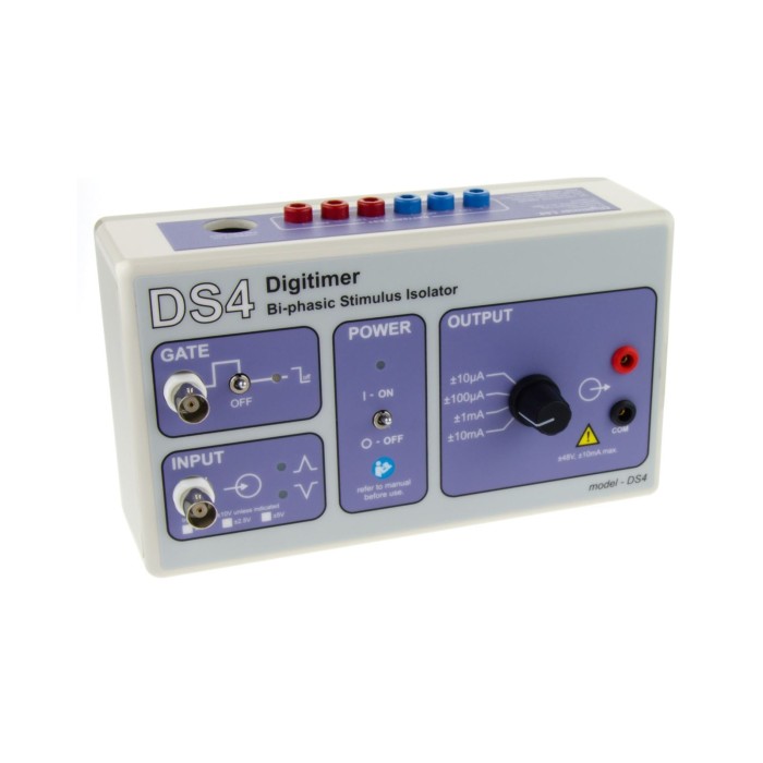
Digitimer DS4 (Bi-phasic Stimulus Isolator)
The DS4 Bi-Phasic Current Stimulator is a stimulus isolator that can output a bi-phasic isolated constant current stimulus in response to an external command voltage signal. It accepts different input voltage ranges (±1V, ±2.5V, ±5V, ±10V) and produces four current output ranges (±10µA, ±100µA, ±1mA and ±10mA).
Please note: Important! This product is for research applications only. Not a medical device as defined in EU directive 93/42/EEC. Not designed or intended to be used for diagnosis or treatment of disease.
The DS4 Bi-Phasic Current Stimulator takes an analogue voltage waveform defined within your own data acquisition/control (DAQ/DAC) system and converts it into an isolated constant current stimulus. The DS4 accepts different input voltage ranges (±1V, ±2.5V, ±5V, ±10V) and produces four current output ranges (±10µA, ±100µA, ±1mA and ±10mA).. It also features a GATE input, so that several DS4 units can be controlled by a single analogue waveform, but enabled individually via this GATE input. A timed "inactivity sensor" reduces battery usage and damaging "leak currents" during infrequent stimulation, while at the same time maintaining low levels of zero crossing distortion for repetitive waveforms.
Low Noise Isolated Output Stage
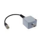
The DS4 features a DC supply to power the control circuitry. The stimulation voltage, however, is generated from two banks of batteries in the low noise, optically isolated output stage. The DS4 is driven by a biphasic voltage waveform which it converts into a proportional constant current stimulus. This means that the DS4 can produce monophasic or biphasic stimuli which can vary in shape from rectangular pulses to sine waves or even arbitrary waveforms. The DS4 features two input sockets. The main INPUT socket is where the voltage command signal is applied and the optional GATE input may be used to turn stimulation on and off using TTL logic, rather like a “soft on/off switch”.
Stimulate with Arbitrary Shaped Waveforms
As the DS4 operates like a voltage to current amplifier, the stimulator has specfic frequency response characteristics, which determine how well it can follow rapidly changing or high frequency command signals. The frequency response plot for the DS4, illustrating the performance when a ±5V input is applied with the DS4 set to a maximum input range of ±10V, an output range of ±10mA and a load of 1kOhm. The graph shows that the -3dB roll-off is at 50kHz, while the expected DS4 output is constant for frequencies up to 5kHz.
Please note: Important! This product is for research applications only. Not a medical device as defined in EU directive 93/42/EEC. Not designed or intended to be used for diagnosis or treatment of disease.


 Australia & New Zealand
  Canada
  European Union (EU)
  France
  Germany
  Japan
Japan  Switzerland
  USA
USA  International